Electronic DC-DC converters for practical applications use switching technology. DC-DC switching power supplies store energy temporarily and then release it through the output voltage, which can be converted from DC voltage to higher or lower voltage DC. The energy can be stored in either an electric field (capacitor) or a magnetic field (inductor or transformer). This conversion method can be step-up or step-down, and the switching efficiency can reach 75% to 98%, which is better than the efficiency of linear voltage regulator because it will consume the unwanted energy in the form of heat.
For efficiency reasons, the semiconductor components in it have to be turned on or off at a fairly fast rate. However, because of the fast transients and the stray components that will be present in the circuit layout, it makes the circuit design more challenging. The high efficiency of switching power supplies reduces the size or volume of the heat sink and also enhances the time portable devices can operate when powered by batteries. In the late 1980s, because of the advent of power-level field-effect tubes, there can be lower switching losses at higher frequencies than power-level bipolar transistors, so efficiency can be further improved, and the drive circuit for field-effect tubes is also simpler.
Another important breakthrough in switching power supplies is the replacement of flywheel diodes with synchronous rectification technology for power-stage field-effect tubes, which have a lower conduction circuit and can also reduce switching losses. Before the widespread use of power semiconductors, low-power DC-DC synchronous rectifiers included an electrical and mechanical oscillator, and the oscillated electricity was output through a step-down transformer to a vacuum tube, a semiconductor rectifier, or a synchronous rectifier connected to the oscillator.
Most DC-DC converters are designed for unidirectional conversion, where power can only flow from the input side to the output side. However, all switching voltage converter topologies can be changed to bi-directional conversion, which allows power to flow from the output side back to the input side, by changing all diodes to independently controlled active rectification. Bi-directional converters can be used in applications like vehicles that require regenerative braking, where the converter is supplying power to the wheels while the vehicle is running, but when the brakes are applied, the power is in turn supplied from the wheels to the converter.
Switching DC-DC converters are actually more complex from an electronics point of view, but because many of the circuits are packaged in integrated circuits, fewer parts are required. In circuit design, careful circuit design and actual circuit and component layout are required to keep switching noise down to a tolerable level and to allow stable operation of high frequency circuits. For buck applications, switching converters are more expensive than linear converters, but with the advancement of chip design, the cost of switching converters is gradually decreasing.
DC-DC converters can be composed of integrated circuits plus a few parts, or the converters themselves are complete parallel integrated circuit modules that only need to be assembled on a circuit board to be used. A linear voltage regulator can convert a stable DC voltage from a higher voltage but possibly unstable DC voltage source, and the power corresponding to the difference between the input and output voltage is converted into thermal energy dissipated according to Joule’s law, which can be considered as a DC-DC converter by definition, but in practice, linear voltage regulators are rarely called as such.
Resistive voltage divider circuits can also produce output voltages different from the input voltage, possibly with the addition of a voltage regulator or Zener diode to regulate the output voltage, although they are also rarely called DC-DC converters. There are also capacitive voltage doublers and multipliers that can double, triple, or other integer multiples of the DC voltage, and are mostly used for applications with small output currents.
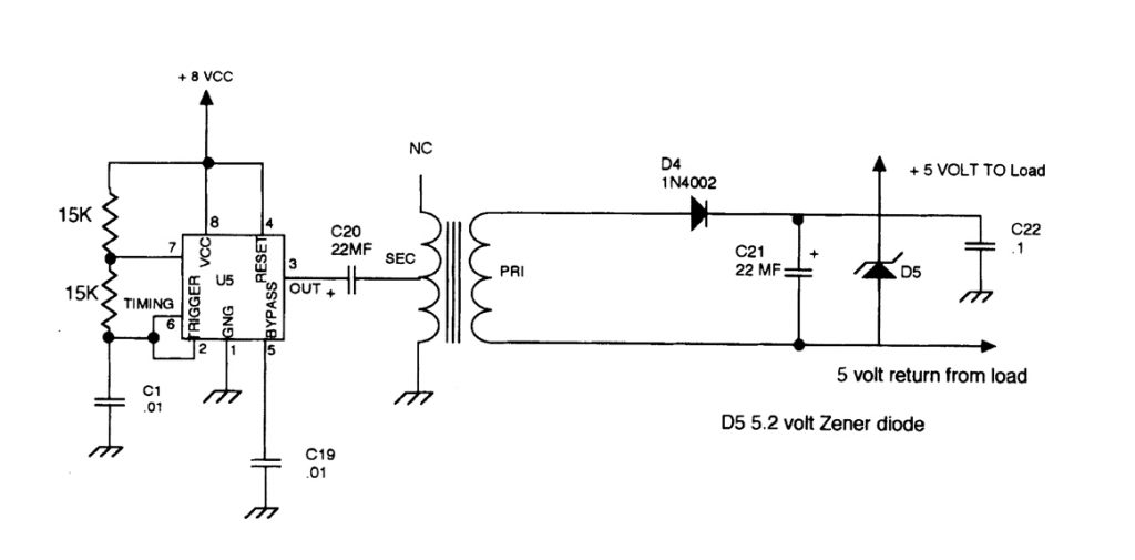
These DC-DC converters periodically store energy in a magnetic field generated by an inductor or transformer, and then periodically release the stored energy in the range of 300 kHz to 10 MHz. The converter is controlled by adjusting the duty cycle (the percentage of on time in the cycle) to adjust the input current, input voltage or to maintain a fixed power output. A DC-DC converter with a transformer can provide an output voltage that is isolated from the input voltage. What is commonly referred to as a “DC-DC converter” is actually a magnetic field storage converter, which is also the core component of a switching power supply. There are many different configurations.