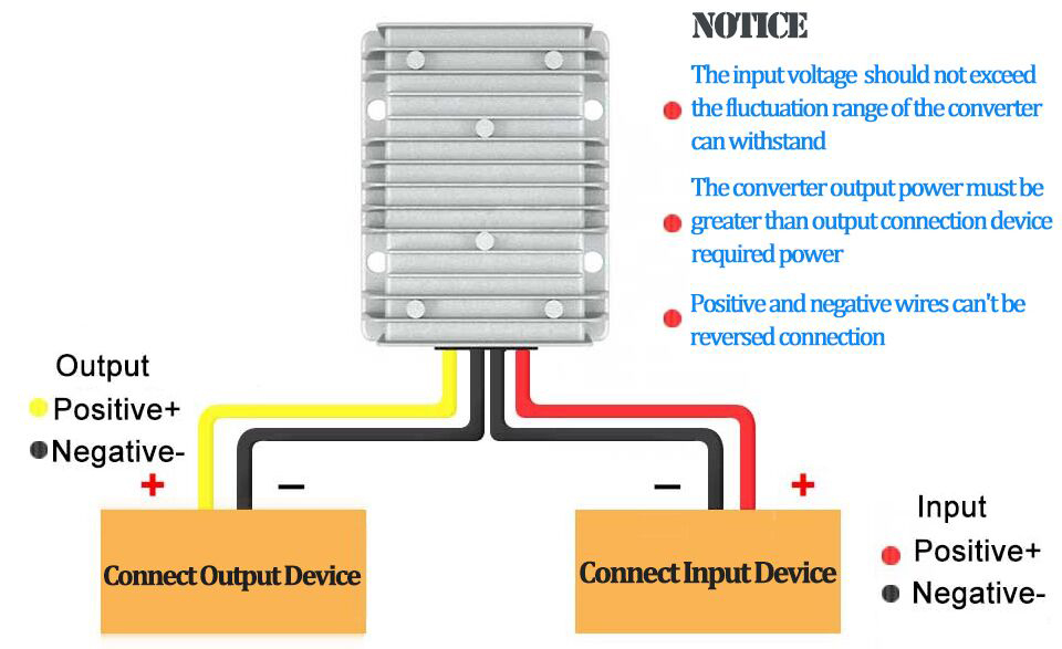
DC-DC converter is a DC conversion device that inverts (boost or buck) DC power into AC power first, and then rectifies and converts it into another DC voltage. Commonly used DC-DC converter equipment is generally a complete power supply system consisting of DC-DC converter module, monitoring module, and matching user interface board and DC distribution unit, etc.
The power circuit mainly includes the DC input filter circuit, DC-DC converter circuit, DC output filter circuit and the part of auxiliary power supply.
The DC-DC converter circuit mainly includes the converter circuit and the rectifier output circuit, which are the important parts of the whole converter module. The auxiliary power supply circuit provides DC operating voltage for the control circuit, and also provides DC input voltage sampling. The control circuit mainly includes DC-DC converter control circuit, protection circuit, output voltage error amplifier circuit, and digital display, alarm and communication circuit.

The DC input filter circuit contains anti-surge devices, differential mode and common mode filters. In case of lightning or other high-voltage surges, variable resistors and transient voltage suppressors can protect the converter from shocks. The differential mode filter and common mode filter can effectively suppress the high frequency noise generated inside the module, and also make the interference from the DC input power supply not affect the normal operation of the module.
The converter module is responsible for converting the DC voltage and consists of two major parts: the power circuit and the control circuit. The power circuit realizes the conversion from DC input to DC output; the control circuit provides all the control signals required for the power conversion, including feedback loops, DC signal processing, analog and switching processing circuits, etc.
The DC-DC power converter is a device that has to go through four stages – voltage transformation, rectification, filtering and voltage stabilization – to complete the conversion of AC power into regulated DC output voltage.
Power transformer is a step-down transformer, it will transform the grid 220V AC voltage into the required AC voltage, and sent to the rectifier circuit, the transformer ratio is determined by the secondary voltage of the transformer. Filter circuit can filter out most of the AC components in the output voltage of the rectifier circuit, so as to obtain a relatively smooth DC voltage.
Voltage regulator circuit: The function of the voltage regulator circuit is to make the output DC voltage stable and not change with the changes in AC grid voltage and load.