The first parameter to consider when selecting the right buck converter is the input voltage range. Converters with an input voltage range of 2.5V to 5.5V are best suited for applications powered by a single lithium-ion battery, but can also be used in 5V power supply applications. Converters with an input voltage of around 18V are often used in 12V power supply applications, but are also used in 5V power supply applications because of their wide voltage range. And converters at 21V / 23V / 24V to 80V have a very wide range of applications. The 36V devices are often used in industrial power supply applications such as 24V DC, or automotive applications where there are large fluctuations in power supply such as 13.5V car batteries.
For power supplies used in low power standby mode, it is desirable to maximize the efficiency of the DC-DC buck converter at light load. The switching frequency of a forced PWM type buck converter is constant over the entire load range. If a high switching frequency is used at light load, most of the losses will be caused by switching losses. Buck converters with improved light load efficiency reduce the switching frequency at light load, which is often called pulse omission mode. The operation principle is as follows: when the load is reduced, the inductor current valley will drop to zero at a specific point, and in the case of forced PWM type devices, the low-side MOSFET will continue to conduct, causing the inductor current to become even negative.
In the case of a PFM device, the low-side MOSFET is turned off, leaving the switching node floating until the next high-side MOSFET is turned on. The minimum on-time of the high-side MOSFET determines the peak current of the inductor, while the average current can only be reduced by lowering the switching frequency, i.e., by adjusting the internal frequency to omit pulses. The PFM mode reduces the switching frequency of the DC converter to a very low frequency, such as a few kHz, at light load, thus reducing the switching losses and thus greatly improving the light load efficiency.
The switching frequency of a DC-DC buck converter is a very important parameter. Higher switching frequency allows the use of smaller inductors and capacitors, and better response to step loads. However, higher frequencies increase switching losses and increase the frequency range of EMI radiation. A higher switching frequency also limits the maximum achievable buck ratio, because the minimum duty cycle is limited by the converter’s minimum on-time and switching frequency.
Very high frequency buck converters (> 1MHz) are typically used for applications with very low input voltages, such as 5V or lower, because the low input voltage results in lower switching losses and the maximum buck ratio is smaller for such applications. For most 12V applications, a switching frequency of 500kHz is more suitable, allowing for both switching losses and device size. In high current and high input voltage (> 18V) applications, switching frequencies below 500kHz are preferred to reduce switching losses and achieve a high step-down ratio.
Selection criteria for DC-DC buck converter control architectures
DC-DC converter products include a wide range of buck converters with different control architectures, including current mode (CM), current mode – constant on-time, and advanced constant on-time (COT) control architectures. Each architecture has its advantages and disadvantages, so when selecting a buck converter for an application, it is best to understand the characteristics of each architecture first.
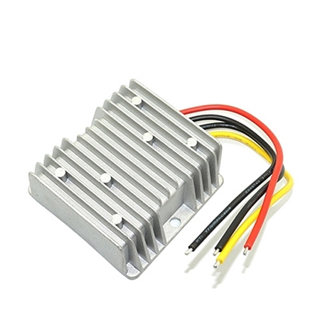
If you have questions about selecting a DC-DC buck converter, ATO recommends two of our top-performing products: the 48V to 24V DC-DC buck converter and the 24V to 12V DC-DC buck converter. Both are watertight and offer excellent efficiency. Buy them now!