DC-DC circuits are circuits in which a DC power supply is transformed into different voltage values. DC-DC is a branch of switching power supply technology, which includes AC-DC and DC-DC two branches. DC-DC circuits are divided by function into:
- Boost converter: A circuit that converts a low voltage to a high voltage.
- Buck converter: A circuit that converts a high voltage to a low voltage.
- Inverters: Circuits that change the polarity of the voltage, there are two types of positive power supply to negative power supply and negative power supply to positive power supply.
Three main branches, of course, when applied in the same circuit there will be boost reverse, buck boost and other functions exist at the same time. the basic circuit of DC-DC converter has three kinds of boost converter, buck converter and boost/buck converter.
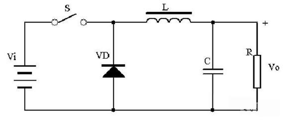
The principle of the buck converter is shown in the figure. When the switch is closed, the voltage added to the terminals of the inductor is (Vi-Vo), at this time the inductor is excited by the voltage (Vi-Vo), and the flux increased by the inductor is: (Vi-Vo)*Ton.
When the switch is off, due to the continuous output current, the diode VD becomes on, the inductor is clipped, and the inductor reduces the flux as: (Vo)*Toff.
When the state of switch closed and switch open is balanced, (Vi-Vo)*Ton=(Vo)*Toff, Vi>Vo due to duty cycle D<1, and the buck function is realized.
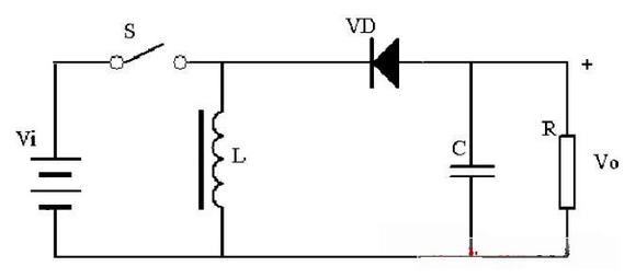
The principle of the boost converter is shown in the figure. When the switch is closed, the input voltage is applied to the inductor, at this time the inductor is excited by the voltage (Vi), and the flux increased by the inductor is: (Vi)*Ton.
When the switch is off, due to the continuous output current, the diode VD becomes on, the inductor is clipped, and the inductor decreases the flux as: (Vo- Vi)*Toff.
When the state of switch closed and switch off is balanced, (Vi)*Ton = (Vo- Vi)*Toff, and since the duty cycle D < 1, Vi .
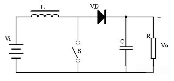
When the switch is closed, the inductor is excited by the voltage (Vi), and the flux of the inductor is increased by (Vi)Ton; when the switch is disconnected, the inductor is clipped, and the flux of the inductor is decreased by (Vo)Toff. When the switch is closed and the switch is disconnected, the increased flux is equal to the decreased flux, and (Vi)*Ton=(Vo)*Toff, depending on the value of Ton over Toff, it is possible that Vi< Vo or Vi>Vo.